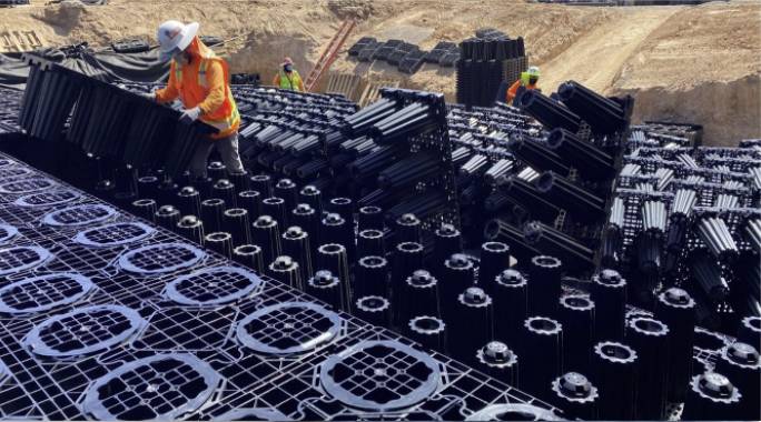
After three years of meticulous research, concentrated development and rigorous testing, ACO introduced StormBrixx; ensuring the product range is the strongest and most easily installed injection molded geocellular product on the global market.
- Maximum Storage – A unique pillar configuration gives high void ratios of 95% for HD and 97% for 300/SD.
- Ease of Installation – Functional design combined with an intelligent snap-lock system make for easy handling and rapid installation times.
- Logistical Efficiency – With the quantity of trucks necessary to transport being greatly reduced due to stackable modules, the savings in both time and money are considerable.
- Strength & Stability – When constructed, the load-bearing pillars of the system precisely align above one another so that loads are evenly distributed downward.
- Access & Inspection – The open cell design allows easy inspection for sediment build-up throughout multiple points within the system.
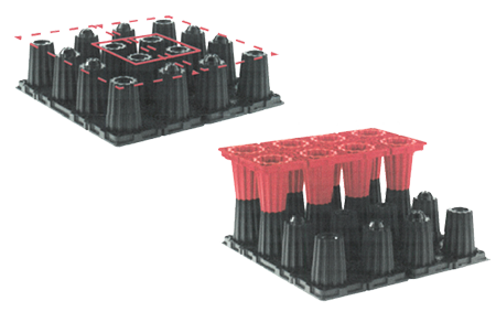
ACO StormBrixx half-modules snap and lock into one another vertically by simply placing one atop the other. Layers and adjacent modules are attached using a basic snap-lock system consisting of male and female connectors that audibly lock into place during assembly.
Each half-body consists of eight pillars, four male and four female. When installing the half-bodies next to each other (ready for brickbonding), units should be matched to one another. If the half-body finishes with a female connection, the next half body should start with a female connection. This will then allow a further half-body piece to be placed on top, bridging the two units, and securely locking the system together. This provides an exceptional level of structural support throughout the system.
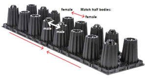
Brickbonding
Brickbonding is a technique to interlock the modules together in an overlapping manner. This method can be performed in both horizontal directions, ensuring that tanks of any size can be assembled and fully interlocked creating one solid, rigid structure.

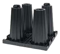
Cutting the Tank Body
The half-body can be cut along the central rib using a handsaw or jigsaw. Each cut piece can be linked to the rest of the system using layer connectors. Cut surfaces must face into the center of the tank system to allow side panels to be attached.
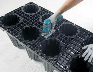
Each half-module is easily assembled by plugging together the individual components (male and female). The half-bodies are assembled with interlocking pillars to optimize the positional safety of the overall system. To achieve this, four push-fit connections must be positioned next to each other.
The StormBrixx system is easily configured to site-specific requirements. Irregular shapes can also be achieved, so the system can be constructed to avoid tree pits, buildings and other ground constraints. Half-layer options are also available for areas with depth restrictions or high water tables.
Functional design combined with an intelligent snap-lock system make for easy handling and rapid installation. Small openings at the base of the pillars allow water to fill and drain. This allows the pillars to form part of the high void ratio.
Guide to installing ACO StormBrixx® systems
The information on this page should be considered as general advice only. ACO offers this guidance in good faith and if in doubt, engineering advice should be sought. Installation dimensions and methodologies will vary by site. Local ground conditions and council design requirements should be adhered to.
Step 1 – Excavate Site
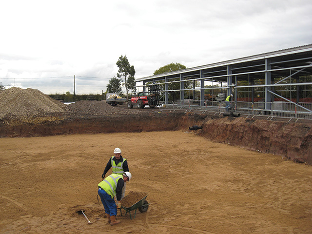
Excavate trench to required dimensions to receive StormBrixx® tanks, allow additional 24″ (600 mm) on all sides for access, placement of side panels and necessary pipework, etc. The foundation (subgrade) of the subsurface storage structure is an extremely important part of the module system installation, as this is the location where the system applies the load generated at the surface.
Step 2 – Lay Subbase
Ensure base of excavation is smooth, level and capable of withstanding required design loads, angle sides of excavation to prevent collapse, and ensure safe access/conditions for site workers. Please refer to local, state, federal standards for guidance. Base of excavation must be uniform, level and free of debris and soft or yielding subgrade areas. Compact to at least 95% standard proctor density (or as required by engineer) unless infiltration of stormwater into subgrade is desired.
Step 3 – Lay Liner/Geotextile
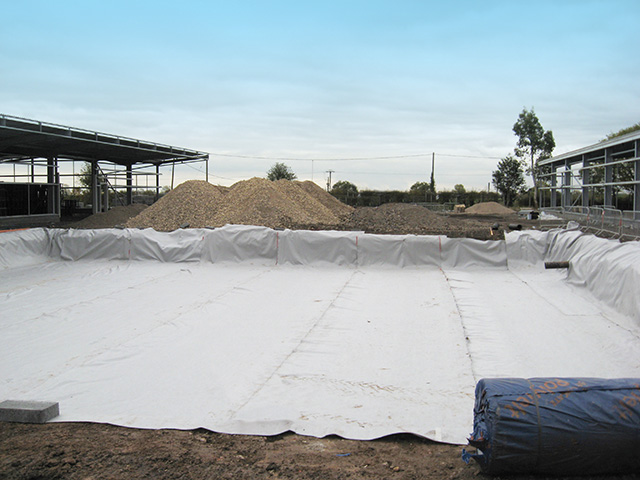
Lay geotextile to base sides of the excavation with minimum 12″ (300 mm) overlap at joints. Inspect geotextile for damage. Install geomembrane liner to required standards and if required, with minimum 12″ (300 mm) overlap at joints. Note: Infiltration systems do not require geomembrane.
Step 4 – Assemble ACO StormBrixx Tanks
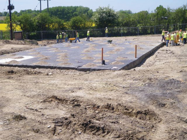
Assemble StormBrixx units to required size and configuration, utilizing the brick-bonding method and place on geotextile/geomembrane. Ensure loose units are fixed together using StormBrixx® layer connectors.
Step 5 – Install Layer Connectors
SINGLE LAYER SYSTEM – If only one layer of ACO StormBrixx is installed, no connectors are required. Laying StormBrixx in the brickbonding pattern provides additional stability for the overall system. MULTIPLE LAYER SYSTEM – Layer connectors are used if two or more layers of StormBrixx are installed. Two individual connectors snap together and are inserted between the individual layers as positional fixing. This helps prevent lateral movement between layers.
Step 6 – Build Access & Inspection Points
Access can be gained to the ACO StormBrixx system by using a Remote Access Unit. These units can be installed both within the structure and on the outer edges. They replace a half-length StormBrixx module within the layers. With multi-layer systems, the units stack on top of each other and integrate with the StormBrixx modules. Access can also be achieved using the Remote Access Plate. This plate is located within the overall system. Modules are removed to create free movement for inspection and cleaning of the system. With the access plate, an easy installation is possible at any desired position apart from the perimeter edge of the tank.
Step 7 – Place Pipe Connections
The ACO StormBrixx system offers pipe adapters that are used for the connection of inlet and outlet pipes as well as ventilation pipes. These are typically located within the side panels of the StormBrixx. Pipe connector sizes range from 4” (100 mm) to 15” (450 mm) markings on the side panels will indicate the different size openings. The openings for inlets and outlets must be cut out before installing the side panels, a sawzall with an extra-long saw blade is recommended. The pipe adapter is mounted in opening made in the side panel and fixed securely. The geotextile is cut and pushed over the pipe and sealed, carefully cut geotextile/liner around pipe protrusions. Seal geotextile/liner around pipe connections. Test all joints for leaks and ensure top covers are installed on top layer of tank system. Remote access units also accommodate pipe connections. Each unit has markings that will indicate the different size openings that can be cut out to accommodate various pipe sizes 4” to 18” (100 mm to 450 mm). To create an opening within the remote access unit, drill a hole to insert a saw blade and cut along the template provided.
Step 8 – Wrap System in Membrane Liner or Geotextile Fabric
Upon completion of ACO StormBrixx assembly continue to wrap modules in geotextile fabric and/or membrane liner.
Step 9 – Connect Inlet/Outlet Pipes
Connect inlet/outlet/vent pipe and remote access units using appropriate pipe connectors and pipe sizes ensuring each connection is sealed correctly.
Step 10 – Backfill Sides
Backfill evenly around excavation sides using angular stone or well-graded granular soil/aggregate. All material is to be placed evenly in 12” (305 mm) lifts around the system and aligned with a vibratory plate compactor.
Step 11 – Backfill Top
Place backfill material over the top of the StormBrixx® system and then backfill. There should be a minimum 20″ (500mm) backfill cover before compaction equipment is used. Use an excavator, dozer, or conveyor boom to dump backfill material adjacent to StormBrixx tank, then push material over the system. Use a walk-behind plate vibrator to settle the backfill and provide an even distribution in maximum 12” (305 mm) lifts. Backfill must meet requirements listed in specifications, suitable materials are as follows: well-graded granular soil/aggregate, typically road base or earthen fill (maximum 1″–3″ [25–80 mm] particle size) crushed angular stone placed between modules and road base or earthen fill.
Step 12 – Secure Installation
To prevent damage to the StormBrixx units, the installation should be secured to prevent unauthorized traffic from driving over the system. Projects nearing completion should use warning tape or temporary fencing to secure the installation. Regardless of what method is selected to secure the installation, it must remain in place until construction activity has concluded and no further access of heavy vehicles is required.
Step 13– Completion
Complete pavement construction or landscaping over StormBrixx system. Once all steps are complete the system is ready for use.
It is important to note that failure to control and remove sediment build-up in stormwater tanks is the largest cause of system failure. The open design of ACO StormBrixx allows the system to be inspected by remote CCTV either through the inlet connection, remote access unit, remote access plate, or inspection points. This allows the system to be inspected for sediment build-up and enables collected sediment to be removed from the infiltration system or flushed through a detention/retention system.
As sediment has the potential to carry high levels of pollutant, it is important that any sediment removed from the system is disposed of by an authorized contractor and in accordance with local, state and federal regulations.
Maintenance Steps
Step 1
Locate the access cover on the surface connected to the tank.
Step 2
Once located, safely open the lid and place it out of the way.
Step 3
Perform an inspection of the tank to locate any debris. This can be done visually, with or without an inspection camera.
Step 4
If your tank has standing water in it already, you will need to vacuum and remove that water first before visually inspecting the tank.
Step 5
Use the high pressure jet nozzle or wand to loosen and suspend any solid debris that has built up.
Step 6
A minimum water pressure of 8 PSI is recommended. The maximum pressure depends on the geotextile fabric chosen. Please check with fabric manufacturer for max PSI.
Step 7
To ensure correct insertion of a high pressure jet nozzle we recommend using a pipe elbow.
Step 8
Once the water level has reached 3 inches or more, shut the water off and remove the high pressure nozzle.
Step 9
Insert the vacuum hose via the remote access unit or access plate and begin removing the debris that is now suspended in water. Do this until all the water has been removed.
Step 10
Not all water and debris may come out in the first round, repeat steps 5 through 7.
Step 11
Once it appears all debris has been removed, inspect the tank again to make sure everything has been cleared.
Step 12
Once the tank is clear of debris and water, remove all equipment used and place the cover back on the tank. Secure cover accordingly.
Alternatively, a nearby fire hydrant can be used to suspend debris within the StormBrixx system before vacuuming up the water.


Strength performance tests carried out on the ACO StormBrixx system have been conducted using methods recommended in the UK CIRIA C680 “Structural Design of Modular Geocellular Drainage Tanks.” Data supplied is supported by qualified third-party independent certification.
Ultimate load-bearing capacity has been established under laboratory testing conditions during short and long-term load testing. StormBrixx® 300 meets H-20 and HS-25 loading conditions, StormBrixx® HD meets H-25 and HS-25 loading conditions, and StormBrixx® SD meets H-20 and HS-20 loading conditions. For more guidance on load performance, click here.
Quality control production testing is carried out on both vertical and horizontal planes on all StormBrixx products produced.
Creep Testing
Creep testing is carried out on both manufactured products and material coupons to ensure confidence in long-term performance. During a creep test, specimens are subjected to a static load. This corresponds to the load placed on the StormBrixx. The strain applied to the StormBrixx is recorded over the course of the test, which lasts 1,000 hours. Using this data, creep curves are generated, which depict the long-term behavior of plastics and lifespan of the product. Based on the data received from these tests, StormBrixx® HD offers a 60-year lifespan and StormBrixx® 300/SD offer 50-year lifespans.
In Situ Testing
ACO installed a StormBrixx SD system complete with sensors to measure vertical deflection and lateral movement. The system was covered with 24″ (610 mm) of native soil with a 1″ (25 mm) black top surface. The data collection during backfilling and traffic by trucks was collected, and monitored by a leading American university. The test was witnessed by a certified test house. A 60,000 lb (30 ton) truck was driven numerous times across the StormBrixx system to simulate dynamic loads with no failure. The truck was also parked above the system to ensure static load requirements were met. Deflection of the system—both vertically and laterally—was deemed acceptable and compliant with H-20 load requirements. If you would like to see the complete testing report, please contact ACO Customer Service.


Comparative Testing of Plastic Underground Geocellular Stormwater Systems
At an independent, certified 3rd party test center, ACO tested a variety of geocellular stormwater detention and infiltration systems. The objective was to determine the structural performance in both a vertical and lateral short term compression test. We tested six different manufacturers’ products to rupture point to determine who has the best structural performance with no safety factors.

