SlabDrain — H Series (Non-Metal Edge)
Non-Metallic Edge – H Series
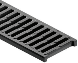
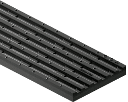
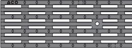
The SlabDrain – H series are ideal for non-metal applications and are available in 4” internal width. The grate seat and channel edge are manufactured from the same polymer concrete as the channel body. Grates are secured with QuickLok locking mechanisms. Even though some Load Class E grates are available, the maximum load class for H-Series channels is Load Class C.


H100-8
4” Internal Width
H100-10
4” Internal Width
QuickLok® grates require a separate locking bar and use a bayonet fitting attached to the grate that is spring-loaded into the bar. These grates are ideal for extra security.
Key
ADA compliant
Compliant with Americans with Disabilities Act of 2010, Section 302.3
Heel-resistant
ASME A112.6.3 - 2001 Heel-resistant slot width less than 0.31" (8 mm)
Heel-safe
Heel-safe slot width equal or less than 0.25" (6.5 mm)
Anti-slip grates
BPN over 24 (test results available)
Bicycle safe
Compliant to Australian Standard AS 3996 - 2006
Non-metallic
No metallic/magnetic parts included

Water Intake
Click these icons to calculate water intake on that specific grate style
| Part No. | Length in (m) |
Slot size in |
Intake area in2 | Calculate Water Intake | Weight lbs | ||||||||
|---|---|---|---|---|---|---|---|---|---|---|---|---|---|
| LOAD CLASS C (EN 1433) - 56,202 LBS – 1,934 PSI (COMMERCIAL VEHICLE TRAFFIC) | |||||||||||||
| SLOTTED PLASTIC |
|
QUICKLOK LOCKING | |||||||||||
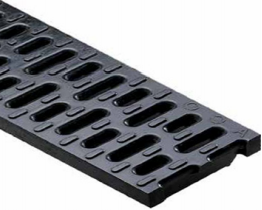 |
Type 492Q - black | 31710 | 19.69 (0.5) | 0.3 x 1.69 avg. | 22.2 | |
3.5 |
✓ |
× |
✓ |
× |
✓ |
|
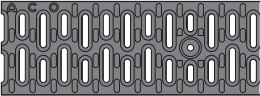
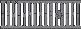
| MOSAIC IRON |
|
QUICKLOK LOCKING | |||||||||||
 |
Type 479Q - iron | 97116 | 19.69 (0.5) | 0.43 avg. | 13.0 | 9.6 |
✓ |
✓ |
× |
× |
✓ |
|
|
QuickLok® grates require a separate locking bar and use a bayonet fitting attached to the grate that is spring-loaded into the bar. These grates are ideal for extra security.
Key
ADA compliant
Compliant with Americans with Disabilities Act of 2010, Section 302.3
Heel-resistant
ASME A112.6.3 - 2001 Heel-resistant slot width less than 0.31" (8 mm)
Heel-safe
Heel-safe slot width equal or less than 0.25" (6.5 mm)
Anti-slip grates
BPN over 24 (test results available)
Bicycle safe
Compliant to Australian Standard AS 3996 - 2006
Non-metallic
No metallic/magnetic parts included
Water Intake
Click these icons to calculate water intake on that specific grate style
| Part No. | Length in (m) | Slot size in | Intake area in2 | Calculate Water Intake | Weight lbs | ||||||||
|---|---|---|---|---|---|---|---|---|---|---|---|---|---|
| LOAD CLASS E (EN 1433) - 135,000 LBS, 4,641 PSI INDUSTRIAL TRAFFIC | |||||||||||||
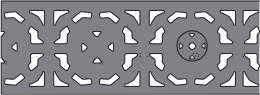
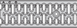
| SLOTTED IRON |
|
QUICKLOK LOCKING | |||||||||||
 |
Type 461Q - iron | 96752 | 19.69 (0.5) | 0.40 x 3.93 | 34.1 | |
10.2 |
✓ |
× |
× |
× |
✓ |
|
| SLOTTED STEEL |
|
QUICKLOK LOCKING | |||||||||||
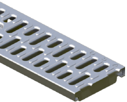 |
Type 435Q - galvanized | 31550 | 39.37 (1.0) | 0.38 x 1.46 avg. | 35.2 | |
13.7 |
✓ |
× |
× |
× |
✓ |
|
| Type 436Q - galvanized | 31551 | 19.69 (0.5) | 17.6 | |
6.8 | ||||||||
| Type 490Q - stainless | 31650 | 39.37 (1.0) | 35.2 | |
13.7 | ||||||||
| Type 493Q - stainless | 31651 | 19.69 (0.5) | 17.6 | |
6.8 | ||||||||
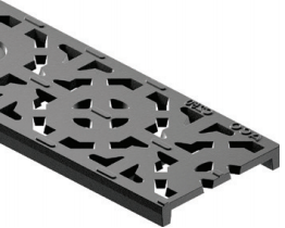
| LONGITUDINAL IRON |
|
QUICKLOK LOCKING | |||||||||||
 |
Type 478Q - iron | 03314 | 19.69 (0.5) | 1.77 x 0.27 | 22.5 | |
13.3 |
✓ |
✓ |
✓ |
× |
✓ |
|
QUICKLOK® - BOLTLESS LOCKING SYSTEM
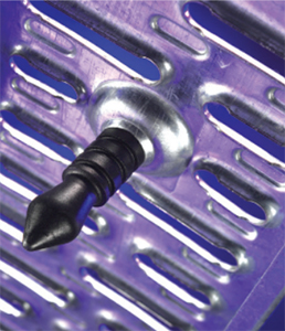
Comprised of either a glass nylon stud or steel pin fitted to grate and a removable QuickLok® bar in channel, QuickLok® locks grate to channel by aligning stud over locking bar and applying pressure until they snap together. With no loose bolts or bars, QuickLok® provides a highly secure boltless lock that is still easy to take apart for maintenance and cleaning. This saves time and money during installation.
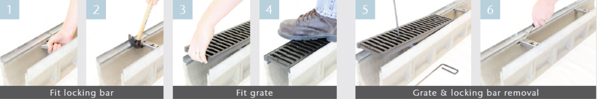
Locate locking bar in channel wall recesses by rotating clockwise.
Use hammer to tap bar into place so that serrated ends grip in recess.
To install grate, align QuickLok® stud directly over locking bar.
Push down or stand on grate until it clocks into position.
To remove first grate, insert grate removal tool into slots at end of grate, pull up sharply. Remaining grates can be removed by hand.
To remove bar, insert screwdriver into hole at end of bar and lever back serrated end, rotate bar free.
 (2)")
| Part No. | Invert Depth [in] | Invert Depth [mm] | Overall Depth [in] | Overall Depth [mm] | Volume [gal] | Weight [lbs] | |
|---|---|---|---|---|---|---|---|
H100-8 | |||||||
| Constant Depth Channel - 39.37" (1 m) | 00985 | 2.56 | 65 | 3.15 | 80 | 1.16 | 20.0 |
| Closing End Cap | 05935 | - | - | 3.15 | 80 | - | 1.0 |
H100-10 | |||||||
| Constant Depth Channel - 39.37" (1 m) | 00549 | 3.35 | 85 | 3.95 | 100 | 1.70 | 25.0 |
| Closing End Cap | 05939 | - | - | 3.95 | 100 | - | 1.0 |
| Part No. | Weight | ||
|---|---|---|---|
 | Debris Strainer for 4" bottom knockout | 93488 | 0.2 |
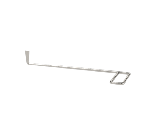 | Grate Removal Tool | 01318 | 0.3 |
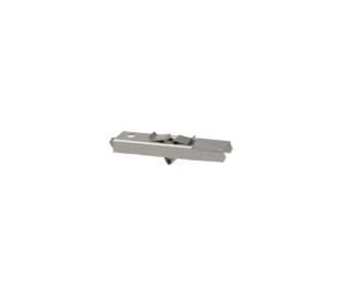 | QuickLok® Locking Bar - 4" System | 02899 | 0.1 |
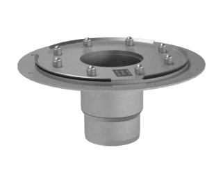 | Membrane No-Hub Drain - Stainless Steel | 01043 | 8.9 |
DR100 ACO Drain Catalog Part 1 – Introduction
DR100 ACO Drain Catalog Part 4 – SlabDrain
DR100 ACO Drain Catalog Part 5 – Technical Support
DL016 Polymer Concrete Install Guide Spanish 2017
DR702 Installation Device Guide
3-Part Specification
3 Part Specification - SlabDrain (Non-Metallic Edge) - General Duty Shallow Depth Trench Drain
Trench Systems
SlabDrain - H100-8 channel system.pdf
SlabDrain - H100-10 channel system.pdf
QUICKLOK LOCKING
H-Series (Non-Metal Edge)
| Description | Documents | |
|---|---|---|
| H Series (Non-Metal Edge) | DWG | |
| H100-8, Class A - Exposed Asphalt Pavement | Download | Download |
| H100-8, Class A - Exposed Concrete Pavement | Download | Download |
| H100-8, Class A - Exposed Paver Pavement | Download | Download |
| H100-8, Class B - Exposed Asphalt Pavement | Download | Download |
| H100-8, Class B - Exposed Concrete Pavement | Download | Download |
| H100-8, Class B - Exposed Paver Pavement | Download | Download |
| H100-8, Class C - Exposed Asphalt Pavement | Download | Download |
| H100-8, Class C - Exposed Concrete Pavement | Download | Download |
| H100-8, Class C - Exposed Paver Pavement | Download | Download |
| H100-10, Class A - Exposed Asphalt Pavement | Download | Download |
| H100-10, Class A - Exposed Concrete Pavement | Download | Download |
| H100-10, Class A - Exposed Paver Pavement | Download | Download |
| H100-10, Class B - Exposed Asphalt Pavement | Download | Download |
| H100-10, Class B - Exposed Concrete Pavement | Download | Download |
| H100-10, Class B - Exposed Paver Pavement | Download | Download |
| H100-10, Class C - Exposed Asphalt Pavement | Download | Download |
| H100-10, Class C - Exposed Concrete Pavement | Download | Download |
| H100-10, Class C - Exposed Paver Pavement | Download | Download |
ACO “How To” Series: End Cap Placement
This video describes how to prepare and install an end cap for an ACO Drain product. While the video displays the method for a 4″ channel, the same method can be used for 8″ and 12″ channels.
ACO “How To” Series: Knockouts
This video describes how to properly remove the knockout portion of an ACO drain for pipe placement. The section of drain used in the video is a 4″ wide trench drain, but the same methods apply to the 8″ and 12″ wide versions as well.
| Project Name | City | State | Product Line | Product Family | Product | Product 2 Line | Product 2 Family | Product 2 | Location | PDF Link |
|---|---|---|---|---|---|---|---|---|---|---|
| University of South Carolina Pool | Columbia | SC | ACO Drain | SlabDrain | H80 | Education | Download | |||
| Veterans Memorial Bridge | Cleveland | OH | ACO Drain | SlabDrain | H100 | Monument/Park | Download | |||
| Buccament Bay Resort | Buccament Bay | St. Vincent | ACO Drain | SlabDrain | H100 | ACO Drain | Brickslot | Brickslot 100 | Resort/Hotel | Download |